S R Latch Truth Table
A Latch is a special type of logical circuit. The latches have low and high two stable states. Due to these states, latches also refer to as bistable-multivibrators. A latch is a storage device that holds the data using the feedback lane. The latch stores 1 -bit until the device set to 1. The latch changes the stored data and constantly trials the inputs when the enable input set to 1.
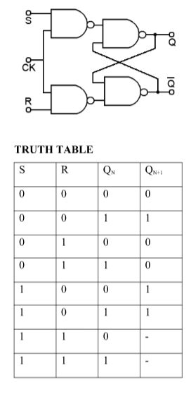
Characteristics table for SR Nand flip-flop Characteristics table is determined by the truth table of any circuit, it basically takes Q n, S and R as its inputs and Q n+1 as output. Q n+1 represents the next state while Q n represents the present state. While dealing with the characteristics table, the clock is high for all cases i.e CLK=1.
Following the truth table for the S-R flip-flop, a negative pulse on the R input drives the output Q to zero. Return to reset state. The time sequence at right shows the conditions under which the set and reset inputs cause a state change, and when they don't. Figure 1 below shows an implementation for SR-Latch with NAND implementation. According to the truth table on the right, S and R are active low. When only S is asserted (S is '0'), the output Q is SET to '1'. When only R is asserted (R is '0'), the output Q is RESET to '0'.
Based on the enable signal, the circuit works in two states. When the enable input is high, then both the inputs are low, and when the enable input is low, both the inputs are high.
Types of Latches
There are various types of latches used in digital circuits which are as follows:
- SR Latch
- Gated S-R Latch
- D latch
- Gated D Latch
- JK Latch
- T Latch.
SR Latch
The SR latch is a special type of asynchronous device which works separately for control signals. It depends on the S-states and R-inputs. The SR latch design by connecting two NOR gates with a cross loop connection. The SR latch can also be designed using the NAND gate. Below are the circuit diagram and the truth table of the SR latch.
Truth Table
| S | R | Q | Q' |
|---|---|---|---|
| 0 | 0 | latch | Latch |
| 0 | 1 | 0 | 1 |
| 1 | 0 | 1 | 0 |
| 1 | 1 | 0 | 0 |
Circuit Diagram
Gated SR Latch
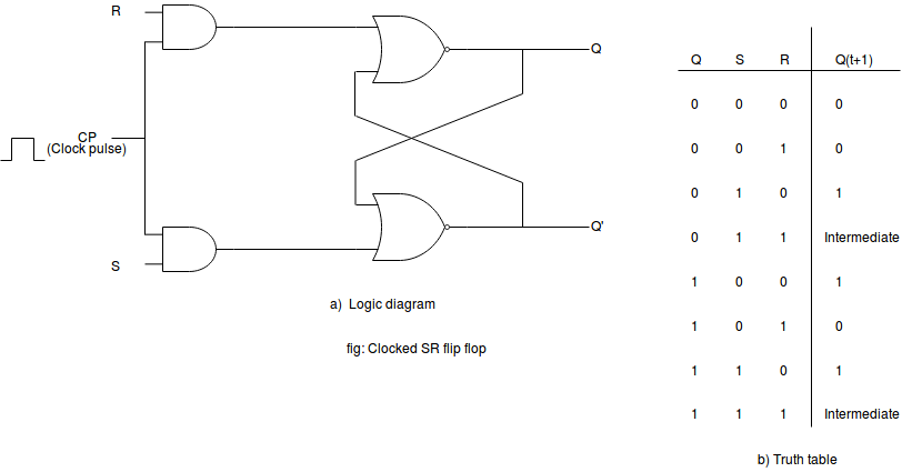
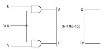
A Gated SR Latch is a special type of SR Latch having three inputs, i.e., Set, Reset, and Enable. The enable input must be active for the SET and RESET inputs to be effective.The ENABLE input of gated SR Latch enables the operation of the SET and RESET inputs.This ENABLE input connects with a switch. The Set-Reset inputs are enabled when this switch is on. Otherwise, all the changes are ignored in the set and reset inputs. Below are the circuit diagram and the truth table of the Gated SR latch.
Truth Table
Circuit Diagram
D Latch
The D latch is the same as D flip flop. The only difference between these two is the ENABLE input. The output of the latch is the same as the input passed to the Data input when the ENABLE input set to 1. At that time, the latch is open, and the path is transparent from input to output. If the ENABLE input is set to 0, the D latch's output is the last value of the latch, i.e., independent from the input D, and the latch is closed. Below are the circuit diagram and the truth table of the D latch.
Truth Table
Circuit Diagram
Gated D Latch
The Gated D Latch is another special type of gated latch having two inputs, i.e., DATA and ENABLE. When the enable input set to 1, the input is the same as the Data input. Otherwise, there is no change in output.
We can design the gated D latch by using gated SR latch. The set and reset inputs are connected together using an inverter. By doing this, the outputs will be opposite to each other. Below is the circuit diagram of the Gated D latch.
Circuit Diagram
JK Latch
The JK Latch is the same as the SR Latch. In JK latch, the unclear states are removed, and the output is toggled when the JK inputs are high. The only difference between SR latch JK latches is that there is no output feedback towards the inputs in the SR latch, but it is present in the JK latch. The circuit diagram and truth table of the JK latch are as follows:
Truth Table
Circuit Diagram
T Latch
The T latch forms by shorting the JK latch inputs. The output of the T latch toggle when the input set to 1 or high. Below is the circuit diagram of the T latch.
Circuit Diagram
S R Latch Truth Table
In digital electronics, a Latch is one kind of a logic circuit, and it is also known as a bistable-multivibrator. Because it has two stable states namely active high as well as active low. It works like a storage device by holding the data through a feedback lane. It stores 1-bit of data as long as the apparatus is activated. Once enable is declared then instantly latch can change the stored data. It constantly trials the inputs once enable signal is activated. The working of these circuits can be done in 2-states based on the enable signal being high or else low. When the latch circuit is the in an active high state, then both the i/ps are low. Similarly, when the latch circuit is then an active low state, then both the i/ps are high.
Different Types of Latches
The latches can be classified into different types which include SR Latch, Gated S-R Latch, D latch, Gated D Latch, JK Latch, and T Latch.
SR Latch

An SR (Set/Reset) latch is an asynchronous apparatus, and it works separately for control signals by depending on the S-state & R-inputs. The SR-latch using 2-NOR gates with a cross loop connection is exhibited below. These latches can be built with NAND gates also; however, the two inputs are exchanged as well as canceled. So it is called as SR’-latch.
Whenever a high input is given to the S-line of the latch, then the output Q goes high. In the feedback process, the output Q will stay high, when the S-input goes low once more. In this way, the latch works as a memory device.
Equally, a high input is given to the R-line of the latch, then the Q output goes low (and Q’ high), then the memory of the latch will effectively reset. When both the inputs of the latch are low, then it stays in its earlier set state or reset state. The state transition table or truth table of SR latch is shown below.
| S | R | Q | Q’ |
| 0 | 0 | Latch | Latch |
0 | 1 | 0 | 1 |
| 1 | 0 | 1 | 0 |
1 | 1 | 0 | 0 |

When both inputs are high at once, there is trouble: it is being told toward concurrently generating a high Q & low Q. This generates a race condition in the circuit either flip flop achieves something in altering first will respond to the other & declares itself. Preferably, both Logic gates are equal and the device will be in an undefined condition for an indefinite stage.
Gated SR Latch
In some cases, it may be popular to order when the latch can & cannot latch. The simple extension of an SR latch is nothing but a gated SR latch. It gives an Enable line that should be driven high before information can be latched. Although a control line is necessary, the latch is not synchronous due to the inputs which can alter the output even in the middle of an enable pulse.
When the input of an Enable is low, the o/ps from the gates must also be less, therefore the Q & Q outputs stay latched toward the earlier information. Simply when the enable i/p is high can change the position of the latch, as shown in the tabular form. As the enable line is stated, a gated SR-latch is equal in the process toward an SR latch. Sometimes, an enable line is a CLK signal; however, it is a read/write strobe.
CLK | S | R | Q(t+1) |
0 | X | X | Q(t) (no change) |
| 1 | 0 | 0 | Q(t) (no change) |
1 | 0 | 1 | 0 |
| 1 | 1 | 0 | 1 |
1 | 1 | 1 | X |
D Latch
The data latch is an easy expansion to the gated SR-latch that eliminates the chance of unacceptable states of input. Because the gated SR latch lets us fastener the output without employing the inputs of S or R, we can eliminate one of the i/ps by driving both the inputs with an opposite driver. We eliminate one input & automatically make it opposite of the residual input.
The D-latch outputs the input of the D when the Enable line is high, otherwise, the output is whatever the D input was whenever the Enable input was last high. This is the reason it is known as a transparent latch. When Enable is stated, then the latch is called as transparent and signals spread straightly through it since if it isn’t present.
E | D | Q | Q’ |
0 | 0 | Latch | Latch |
0 | 1 | Latch | Latch |
1 | 0 | 0 | 1 |
| 1 | 1 | 1 | 0 |
Gated D Latch
A gated D latch is designed simply by changing a gated SR-latch, and the only change in the gated SR-latch is that the input R must be modified to inverted S. Gated latch cannot be formed from SR-latch using NOR is shown below.
Whenever the CLK otherwise enable is high, the o/p latches anything is on the input of the D. Similarly when the CLK is low, then the D i/p for the final enable high is the output.
CLK | D | Q(t+1) |
| 0 | X | Q(t) |
1 | 0 | 0 |
| 1 | 1 | 1 |
The circuit of the latch will not at all experience a Race state due to the only D input is reversed to offer to both the inputs. Therefore, there is no possibility for similar input state. Thus the circuit of D-latch can be securely used in several circuits.
JK Latch
The both JK latch, as well as RS latch, is similar. This latch comprises two inputs namely J and K which are shown in the following logic gate diagram. In this type of latch, the unclear state has been removed here. When the JK latch inputs are high, the output will be toggled. The only difference we can observe here is the output feedback toward inputs, which is not present in the RS-latch.
T Latch
The T latch can be formed whenever the JK latch inputs are shorted. The function of T Latch will be like this when the input of the latch is high, and then the output will be toggled.
Advantages of Latches
Nor Sr Latch Truth Table
The advantages of latches include the following.

- The designing of latches is very flexible when we compare with FFs (flip-flops)
- The latches utilize less power.
- The performance of latch in the design of the high-speed circuit is quick because these are asynchronous within the design and there is no need of CLK signal.
- The shape of the latch is very small and occupies less area
- If the operation of latch based circuit is not finished in a set time, they borrow the necessary time from other to complete the operation
- Latches give aggressive clocking when contrasted with flip-flop circuits.
Disadvantages of Latches

The disadvantages of latches include the following.
- There will be a chance of affecting the race condition, so these are less expected.
- When a latch is level sensitive, then there is a chance of meta-stability.
- Analyzing the circuit is difficult due to the property of level sensitive.
- The circuit can be tested by using an extra CAD program

Application of Latches
The applications of latches include the following.
- Generally, latches are used to keep the conditions of the bits to encode binary numbers
- Latches are single bit storage elements which are widely used in computing as well as data storage.
- Latches are used in the circuits like power gating & clock as a storage device.
- D latches are applicable for asynchronous systems like input or output ports.
- Data latches are used in synchronous two-phase systems for reducing the transit count.
S-r Latch Truth Table
Thus, this is all about an overview of latches. These are the building blocks for sequential circuits. The designing of this can be done using logic gates. Its operation mainly depends on the input of an enable function. Here is a question for you, what are the two working states of latches?